Posts Tagged ‘cars’

Homage to my Citroën

Posted: 16th October, 2011 in Cars
Tags: , , , ,

It is horrendously slow and shares the same levels of complexity and longevity as cutlery, but my Citroen ZX really is quite the work horse!

I drive approximately 120 miles per day to get to work and back and the ZX has returned an honest 51mpg throughout.  I service it myself and have to say that parts are so cheap and easy to come by.  Here are the sorts of views I enjoy from the slightly ripped driving seat each day.

The car is dropping a rather inspiring 68 bhp down to the front wheels here is a 5th gear pull I did the other day as I filmed it covering a respectable 200,000 miles…

From Citroen

I wonder what will be the popular fuel of choice in 20 years time?

In Europe, 2011, it’s safe to say that diesel is currently most popular.  The ACEA winter report 2008 claims 70% of all new cars purchased in France, Italy and Belgium were diesel.  This trend is continuing to further favour diesel.  So what will be top in 2031 then?

Twenty years ago, 1991, diesels were not nearly as popular as they are now.  They were slow, smelly and uncouth!  The tides did start changing around this period however.  The diesel engine was now turbo charged, relatively high revving, refined, cheap to run and best of all it offered respectable performance.   Any petrol head would still be repulsed by this engine, but for the masses, this was just the thing.

Of course, low fuel consumption equates to low CO2 emissions.  Now the European governments are keen to encourage low consumption of foreign oil, this is achieved by heavily taxing fuel, justified by claims on environmental grounds.  Great, we are saving the environment, less fuel burnt means less CO2 released which means less global warming, (that’s what they want you to think anyway)!

Europe is no doubt a leader in diesel tech, but why?

In the late 80’s through to the mid 90’s when Europe was developing and manufacturing diesels, the rest of the world still loved petrol.  There are some good reasons why America didn’t share the same enthusiasm for reducing CO2 as us Europeans back in the 90s, ultimately it comes down to cost!

North America's most popular automobile of all time

It would appear that the American domestic market is driven by lazy advertisers.  Fashion trends dictate that the bigger the car the better.  The consumer is told they want low cost powerful engines, so thats what is made and thats what they buy, a chicken and egg situation.  The only thing to change that attitude will be fuel cost.

Well in days gone by, North America have had little interest in saving fuel, as they are not completely reliant upon foreign oil- they have their own domestic production.  Another big player in the auto industry, the Japanese, appear to have focussed alot of their attention on American requirements.  The Japs always tend to play it safe, not noted for innovation, they could have implemented Rudolph Diesel’s invention on a mass scale but opted out, it seems they still regard diesel as a dirty, noisy fuel and shy away from using it in their heavily crowded cities.  This leaves the  European market left hankering after frugle little cars that sip as little of the heavily taxed black gold as possible.

Lowering fuel consumption requires expensive research & development as well as increased material and manufacturing costs.  This is what holds back the rest of the world from investing.  In Europe fuel is so expensive the consumer is willing to pay more for their vehicle than an American.  However, recently opinons in the US are shifting, $4 per gallon fuel prices have been hitting the headlines for example.  Take a look at what the likes of GM and Toyota are offering.  GM has a brand image built on the American dream of large trucks, so they can’t go building small town cars, instead they are now offering hybrids as part of their lineup.  Toyota have small eco cars as their foothold and again offer hybrids.

Why do Americans generally not have diesel cars then?  The answer is simple, California!  The state of California has the strictest emissions laws in the world.  That’s right, stricter than ‘green’ Europe.

They require that the following emissions are within a strict defined limit:

  • Carbon monoxide, the highly toxic gas.
  • Hydrocarbons, a large contributor to smog air pollution and disease.
  • NOx, the nastiest of all, acid rain, smog illness and ultimately death.
  • Particulate matter, cause of asthma, cancer and found chucked out of London busses at about the height of a baby in a pram.

Now the state of California is leading the way in emissions regulations.  Diesels are essentially outlawed in California, where limits are set out in three simple classes, low emissions vehicle (LEV), ultra low emissions (ULEV) and super ultra low emissions!… (SULEV).  The majority of diesels are incapable of even meeting LEV, (note that all petrols are SULEV or better).  So in Europe we demand SULEV for our petrol vehicles and then it’s a case of one rule for petrol, another for diesel!  The European governments are essentially making special allowances for dirty diesels.  The only emissions that diesel emit less of, is the harmless gas that plants use to respire, CO2.

So, will Europe eventually come to it’s senses and outlaw diesel like California and the rest of North America?  The alternative is to ignore the problem and keep fooling people into thinking that diesel is a fine alternative to petrol.  In the background Euro 6 standards are being agreed, this will force diesels to be less efficient as they are engineered to battle against all of the emmisions equipment required to clean up their exhaust.  In times gone by, standards have been made and manufactors have responded by failing to achieve the goals, so governments simply move the goal posts!

Ultimately it is down to money, in 20 years time oil will still be lying around and it will be sourced from the same places it is found today, hence, I don’t see any shifts, unless Europe decides to actually be green and then petrol really will be the only sensible solution.

Personally I would hope to see lots more use of electricity and innovative hybridisation and down sizing for the forthcoming 20 years.

I got in my Citroen ZX typed the code into the immobiliser keypad, cranked and cranked, but no start.  Panicked slightly, at this point it was 18.30 and I was 60 miles from home.  Gave it another go and voila fired up with the most almighty plume of blue smoke.  The car then drove flawlessly at 70 mph all the way home.

Next day I came to drive it and this time it just wouldn’t start.  Due to my flawless drive home only a day earlier, I knew it wasn’t injector issues.  If it was, the failure would have left me down on power and dropping clouds of black diesel smoke.  Due to running fine once started, it can’t be the last two reasons for not starting listed below:

  •  The glow plugs are not being powered – (won’t start, runs fine once going.)
  •  The stop solenoid is not lifting. (won’t start, runs fine once going.)
  • Air in the fuel (might start and cut out or idle/run erratically)
  • Low compression, ring or valve wear. (driveability and fuel consumption both suffer if you do get it started)

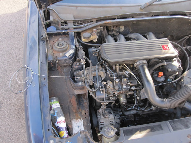
Don’t worry, their is no lift pump to fail, fuel is brought to the high pressure pump via the hand primer found on top of the engine mount on cam belt side, the only failure is for it to allow air into the sytem.

First things first, these engines will very rarely start from cold without red hot glow plugs – cranking simply does not generate enough in cylinder temperature.  They are really easy to check, all you need is:

  • 5 minutes
  • An 8mm spanner / socket
  • A multimeter

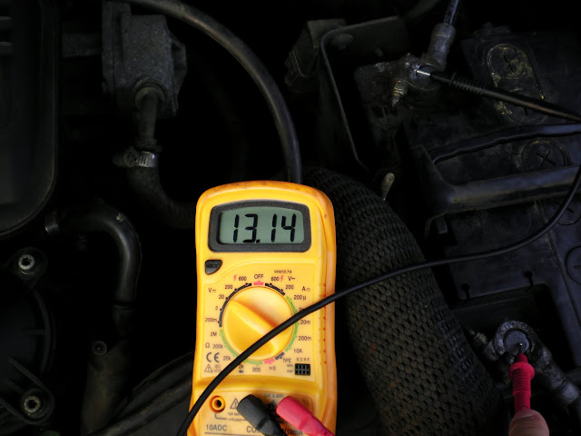
1) Check you have a decent battery.  I set my multimeter up to read in the 20v range and dropped my meter probes onto the battery terminal.  Expect to see well in excess of 12volts for a healthy battery.  With the engine off mine reads 13.14v.

healthy battery

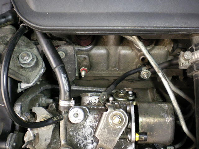
2) Now you need to measure the resistance to ground for each plug.  To get an accurate reading I suggest removing the power supply screwed to the top of each plug.  Look closely in the image below, I have removed the power from the left most glow plug.

Disconnect the power rails to all glow plugs

3) Set your multimeter up to read low resistance, I set mine up for 200 ohm or less.  Now connect the meter’s ground lead to a suitable ground, negative battery terminal is fine.  The positive should go on the top where the power rail plugs, expect a resistance of less than 1 ohm.  My number 1 glow plug measured a corrected 0.7 ohm.  The correction is -0.1 ohm as this is the resistance measured when I touch the two probes together.  If  the glow plug has failed it will read open circuit, giving the resistance of thin air (very very high!!)

glow plug resistance

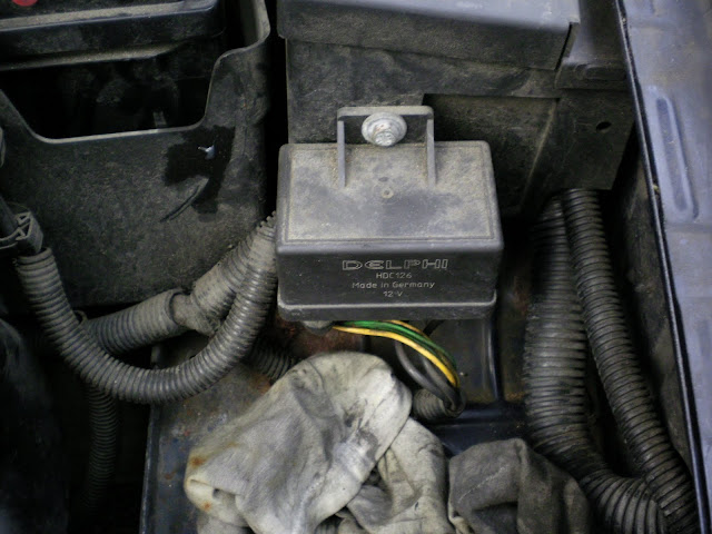
4) Assuming all plugs are in good shape, you MUST check that they are being powered when you turn on the ignition.  Do not skip this step because it is most likely that a sudden no start condition is caused by a bad earth or failed relay box, pictured below.

Relay and timers for powering the glow plugs

5)  So if I think back to school a couple of formulas can be used to theorise what voltage should be read from the power rail feeding all 4 glow plugs.  Assume all plugs measure a corrected 0.7 ohms.

~ Rtot =1/( (1/0.7) x 4)

~Rtot = 0.175 ohms

We can meaure the voltage across one plug, this is essentially acting as a potential divider :

– Vin is the supply voltage acting across the whole circuit, this is battery voltage = 13.14volts in this instance.

– Rtotal is the equivalent of Rtop = 0.175 ohms.

– Rbottom is the resistance measured earlier across one of our glow plugs.  Now we want to measure Vout across that glow plug.

Vout = (0.7 / 0.175 + 0.7) x 13.14

Vout = 10.51 volts

Furthermore we can apply kirchoffs 2nd law: “The sum of the emfs in any closed loop is equivalent to the sum of the potential drops in that loop.”

Applied below, where x = potential drop.

13.14 – x = 4x

13.14 = 5x

x = 2.63

one potential drop is observed at 13.14 -2.63 = 10.51 volts.

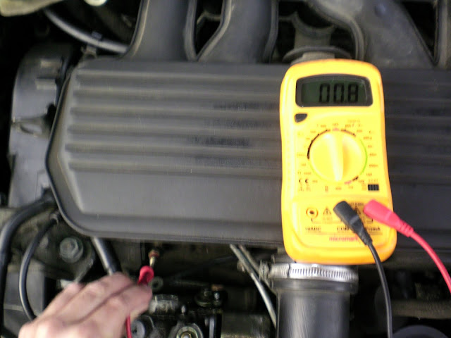
In actual fact I measured a mere 9.43 volts across my glow plug when I turned on the igniton on during glow plug warming period:

The crucial step, power up the plugs and measure voltage on the power rail

The crucial step, power up the plugs and measure voltage on the power rail

So how much heat are these babies pumping out when they get switched on?

V = IR

I = 9.43 / 0.7

I = 13.5A per plug, giving a power of P = IV, P = 127 Watts.

Anyway I seem to have digressed.  Assuming you have power going to your rail and after approx 20 secs you see the voltage across a charged glow plug drop back to ground listen to the relay box as it clicks back.  If something is amiss, try bashing the relay box or simply unplug, clean up the contacts and plug back in.

If you absolutely must get home, I recommend spraying 1-2 seconds worth of easy start parrafin or perhaps even try some WD-40 into the intake!  This has a low flash point and will combust from cold without glow plugs, allowing diesel combustion to initiate.  Beware combustion occurs rather uncontrolled, it causes nasty knocking- potentially damaging big end bearings.  It can also cause the engine to over rev as it burns uncontrollably, that being said, use sparingly better too little than too much.

If those checks confirm glow plugs to be working, it is likely that the failure to start is caused by the stop solenoid. On my car it is used in conjunction with the immobiliser.  When the immobiliser is satisfied you have typed the correct code it sends a message to a unit hidden behind a tamper shield.  This unit, upon receiving the message, drops 12volts across the solenoid and lifts a plunger up.  This plunger is designed to stop fuel from being drawn from the fuel filter into the pump when down.  Check out the suction cup on the bottom, the action of the pump drawing fuel in, actually pulls the plunger on tighter, when in the ‘off’ position.  Here’s what it looks like when removed:

Stop plunger

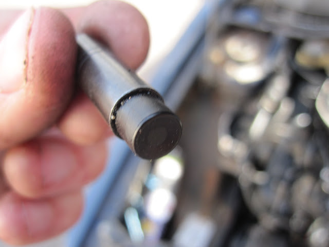
The offending article

So with this stopping fuel flow, my engine was not ever gonna start!  To get to it is not elementary.  The stop solenoid is hidden under a hardened steel shroud.  There are 3 sheer bolts plus a nut and bolt at the bottom stopping any ‘would be’ thief from doing exactly what I needed to do – remove the plunger and therefore allow the engine to start.

I borrowed the services of a local handyman for the afternoon.  He got the shroud off in a couple of hours using a hammer chisel and centre punch to turn the sheer bolts.  And here it is off…

tamper shield

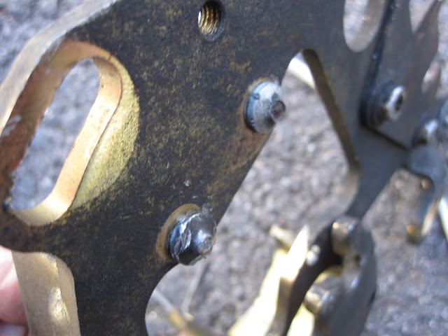
You can make out where the chisel went in to those bloody awkward bolts.  Don’t be afraid to disconnect the high pressure fuel lines and intake manifold to improve access for that chisel to work the bolts round ‘slowly but surely’.  I am told the most awkard of the three is the one at the bottom (blurred in this image, directly below the other two).  He used a mirror to get a visual on the bolt and hit it round with a centre punch.

With the tamper shield off, we pulled the stop solenoid out and watched to see if it popped in and out with the ignition and code.  It did but I reckon that was due to all the disturbance it had had.  I insisted we reassemble the pump with the plunger completely removed from the solenoid to see if the old girl would run.

We had to bleed the high pressure fuel lines as they had been taken out to improve access.  This was achieved, by loosening one at a time, the unions into the injector body and cranking the engine until fuel started coming out at the injector, repeat for all four.  Now I cranked for a further 3 – 4 secs whilst my assistant held the throttle open.  It fired and ran for the first time in a week!  I quickly removed the key from the ignition and of course it kept going.  Beware of doing this, I believe you remove the battery circuit from the alternator whilst it is still generating current, this is not advised and can damage stuff!

I cannot switch the car off any more with the key, I need to pull on the fuel cut off under the bonnet or simply stall the engine in gear.  I could wire a new solenoid to operate off ignition feed but where’s the fun in that?  Instead I simply tug on this rip cord when I’m finished with the car. (see pictures)

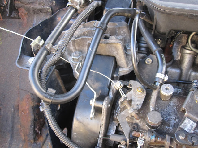
Manual engine shut off

FIXED!

This is a nice project to try out.  It is quite simple, especially for those of you using an OBD 2 compliant petrol car.

If you have a car computer, and want to make a power meter here is how to do it:

Step 1 Figure out how much fuel you are burning. (MAF reporting gasoline vehicles)

  • Using an elm tool or whatever you have to read OBD data, request MAF – PID 0x10 (this is mass airflow) [g/s]
  • Now divide this MAF value by 14.7, this is the magic stoichiometric ratio that fuel needs to burn in air.  For the sake of an engine power calculation we don’t need to worry if the engine is running rich, it is only able to physically burn at this ratio, so any additional fuel is not turned into useful work at the crank.
  • The result of this equation gives fuel mass [g/s]

Step 1 Figure out how much fuel you are burning. (Non-MAF reporting gasoline vehicles)

  • If you don’t have a MAF sensor reported on your OBD you will have to do a speed density calculation, this is less error prone if your car is NA (non turbo).
  • Note engine size in [cc]
  • Gas constanst R = 0.082057 [L atm mol^-1 K^-1]
  • Molar mass of air = 28.75 [g/mol]
  • Estimate Volumetric Efficiency  (this is a definate source of error, browse the web for expected VE figures) for now assume  a vtec engine should be getting around VE = 0.9 at 6500 rpm and at idle assume VE = 0.4, do interpolation to find VE for all other engine speeds, or make a lookup table.
  • Prepare to request the following PIDs:
  • Engine speed (PID 0x0C) [RPM] (raw/4)
  • MAP – Manifold air pressure (PID 0x0B) [kpa] (raw = value)
  • MAT – Manifold air temp (PID 0x0F) [degC] (raw + 40)
  • Work out airflow with the following formula (adding 273 to MAT converts to degrees Kelvin)
  • Airflow [g/s] = (MAP/100) * (Eng_speed/120) * (EngSize/1000) * (1/(MAT+273)) * (1/R) * 28.75 * VE
  • Fuel flow [g/s]  = Airflow / 14.7

Step 2 Estimate engine power

The net calorific value of petrol in the UK is about ~ 43 MJ/kg depending on what fuel station you go to!  The rather poor efficiency of our beloved internal engine is ICE_eff ~ 0.33 (33% is thermal loss to the cooling system and a further 33% goes to bearing and pumping losses).

Power [kW] = 43 * fuel flow [g/s] * ICE_eff

Power [bhp] = power [kw] * 1.34 (look at my previous post to calculate torque)

There we have it.  Have a fiddle with the engine efficiency value, it should not really exceed 0.36, let me know how you get on.

I have rather an obsession with data. Combine this with my deep love of cars, and you may begin to understand why I installed a computer in my car. It is a way for me to collect data whilst I drive!

The Japanese temptress

The Japanese temptress

The opportunities are endless, for example, I want to log acceleration, record videos using an on board camera, monitor gps position, develop a power curve plotter similar to this, as well as monitor fuel consumption data.

Unfortunately my car is not a CAN vehicle, infact it doesn’t even have an OBD II port. With all OBD II cars it is possible to calculate fuel consumption. Obviously some of the other requirements are already quite bespoke. So I am quite prepared to integrate my own sensors, write software etc.

This first post is really an opportunity to discuss what I did to build and install a car PC in my ’94 model year MX-5.

The spec is as follows:

HARDWARE

  • Motherboard : Intel Desktop Board D945GCLF2 (onboard graphics and soundcard)
  • Memory : 2GB Kingston DDR2 800Mhz
  • Power supply : M2-ATX 160W
  • Hard disk drive : 30GB Kingston SSDNow V-Series SATA 2.5″
  • Wifi : Edimax EW-7711UAn
  • GPS antenna : Sanav TK-158
  • Case : Automotive spec case
  • Volume control : Hacked PS/2 mouse with volumouse
  • Touchscreen : Linitx 7″ widescreen touch
  • External HDD : Good ol’ USB stick (TBA)
  • Sound : Sony CDX headunit with aux plugging into on board sound
  • Accelerometer : Freescale MMA8450Q (Donated to me by work, perhaps not recommended if you are going to buy one)
  • Accelerometer interface : Seeeduino, (Arduino clone)

SOFTWARE

  • O/S : Windows XPwith enhanced write filter (to protect the solid state HDD from lots of writes!)
  • Front end : Riderunner
  • Skin : Elite lite
  • GPS : PC Navigator 10
  • Visual Basic 10 to write logging software.

To install a PC in my small little MX-5 was actually not too bad.  I started by removing the spare wheel from the boot.   I then looked at installing the screen in my double DIN dash.  Here are some lovely pictures of the process which was quite fun.

I had to cut into the plastic to allow me to route the sound and monitor cables to the boot, notice the silver tape on the left used to ensure there were no burrs.  Check out my handbrake, my girlfriend gave it a good varnish, the gear nob has now been done but not in this photo.

The headunit acts as my amp, setup on AUX plugging to the computer.  It is secured in place by velcro.  This means I can pull the kit out easily for ‘bench’ maintenance.  I have been able to keep RDS traffic updates as it is still plugged to my FM aerial, I also plan to run a fibre optic cable to the IR receiver.  This is a cheeky way of manipulating the headunit using my remote control 🙂

I went to B&Q and managed to get a large strip of MDF board back for the false floor in my boot.   I cut it exactly, using old wallpaper as a template for my jigsawing.  Now I can use the boot, without worrying about squashing the computer!

Ordering all the bits was done over the weekend, so imagine my excitement when it all arrived at work, I built it and took these photos:

I will put some more bits and pieces up in due course, as I said at the beginning of the post, just a taster of what was involved so far.

I’m talking about that age old argument between diesel fans (who like to talk about torque) and petrol heads who claim power is most important.  My vote is power all the way, and here is why…

Torque:

Say we need to tighten a nut up.  Doing this without a spanner will not get you very far, why? because you need lots of torque.  Torque includes two things-  force AND distance.  For example, slamming a door by pushing on it next to the hinge will not make it slam, that is because the force may be large but the distance between point of rotation and acting force is small, so the torque is low.  Infact even an incredibly strong man with no tool will not be able to tighten a nut as much as a child with a spanner.

So our strong man ‘Arnie’ tightens the nut using only his very strong fingers.  Now a child comes along to undo the nut, without a spanner he’s helpless.  With a spanner, the child now applies a comparitively small force to the spanner but this force acts a long way away from the centre of the nut the longer the spanner is, the easier (or less forece) required to undo the nut.  Try this with a door.  See how hard it is to close the door if you push near the hinges, compared to if you push near the handle.

Taking this example and applying it to a car, the engine has now become our strong man/weak child and  the car’s gearbox is considered to be the length of the spanner.  The nut we were tightening is of course the road applying an opposing force on the car’s wheels.

Power:

Say we need to tighten up 100 nuts, engineers refer to this job as ‘work done’ (which is equivalent to ‘energy’).  Doing this without a spanner would probably be a lot quicker, why, because you don’t have to tighten the nut up by travelling through a large arch/distance.  Speed is the relationship of distance : time.  If we have less distance to cover and we turn nuts at the same rotational speed it will always use less time.

If you don’t believe me, drive 10 miles at 10 miles an hour and then do only 1 mile at 10 miles an hour- the latter surely won’t use up as much time!

So if Arnie and the child both complete the same amount of work in the same amount of time, they are said to have the same power.

Transition to the car example.  Two cars of equal weight have to tow a caravan up a hill.  One car has a lovely (sarcasm) torquey diesel engine, the other has a racy motorbike engine.  The work done will be the same, (same hill, equal weights).  So which one will get there first?  Well it’s all about power.  Power is of course, work done per unit time.  So if you get your work done quicker you finish first.

Interestingly, these vehicles make power in very different ways.  Rember Arnie and the child, well the diesel engine is our strong man- he can afford to spin things slowly because he has lots of torque (strength).  The motorbike engine and child have relatively little strength but a gearbox/spanner provide a torque/strength multiplication.  Like all things in engineering, if you fix one issue, another one is introduced.  By using the gearbox as a torque multiplier you must operate more quickly to keep your work output high.  This is why motorbike engines have to rev so much.

For those interested, a new school SI unit engineer like myself uses the following formula to work out power in kW:

Power [kW] = Torque [Nm]  * EngSpeed [RPM] * (2*3.142/60000)

In the brackets above we are converting engine speed into radians per second and watts into kilo-watts.

To convert kW into brake horsepower, BHP = kW * 1.34

So, What’s Best?

If you want to win a drag race, you need lots of power.  Simple, that is the answer to the question.  If you want to tow your caravan to the top of the hill before all the other caravans you still need to have the most power!  The subtly is the gearbox that denotes the relationship between road speed and engine speed.  Towing caravans up hills requires lots of torque at the wheels even to get rolling.  This can be done by a weak or low torque engine geared to do many more revolutions for each turn of the cars wheels.  Or perhaps a high torque engine, geared to do similar revolutions as the wheels it is driving.  In a towing race, the higher powered engine will always win!  And it doesn’t matter which engine produces more torque (provided they both have a suitable gear box) .

Most diesel fans will claim that this means lots of revving of the less torquey engine to keep up.  Yes this is true, but so what- thats why you have a gearbox and a red line almost double that of the average diesel!  Also, in favour of the smaller less torquey petrol engine is the weight advantage.  By minimising weight you reduce the amount of work needed to complete a race/sprint.

The only real advantage of high torque is longevity.  By creating  power at low engine speeds, service life is dramatically enhanced.  It is also possible to observe fuel savings by keeping engine speed low, as frictional losses are less significant at low speeds, and are zero when the engine is stopped!

In Summary

Cars, trucks boats have all been designed to speed things up.  Whether it’s getting to work quicker in a car compared to walking.  Or perhaps transporting building materials from A to B.  These jobs took a lot longer before the benefit of powerful engines.  Low power means less work done for a given period.

Before starting this tutorial on changing and installing a new differential for your MX5, have a look at  this link if you are interested / unsure what a differential is or how it works, this provides a good explanation.

Prepared for replacement

Diagnosing the problem

Diagnosing a problem is actually quite easy once you understand what’s going on.  Anyone who drives will have at some point heard a funny noise or felt something wasn’t quite right.  This is the first stage to fixing a problem- identify that one exists.  I will now work through the logic of diagnosis.

In my case the interior of the car was filled with an awful whining sound.  I know it can’t be a wheel bearing, experience tells me they make a lower “wub wub wub” noise.  Secondly this is usually only heard when the car is rolling, (regardless of acceleration, coasting etc).   Also, expect for wheel bearing noise to increase or decrease depending on cornering loads. In my case the sound went away when i rolled along in neutral.

We now know that by removing the power the noise goes, hence, it must be ‘powertrain’ .   Powertrain components essentially consist of engine and gearbox.  It can’t be the engine, the noise was not changing with engine speed.  Stop and think, if revving the engine does not immediately speed up the whine, it can’t be connected to the engine- and my sound wasn’t.  In fact, if the diff  is failing, the frequency and pitch of the noise must be directly linked to road speed.  Road speed is associated with gearbox and in particular the output of the gearbox, consisting of the layshaft, final drive and differential.

Identifying the component making a loud whining noise is not easy, the noise fills the cabin.  In the end I made an informed guess!  With some input from my Dad and a work colleague, it was decided that the most likely culprit on my car- a Jap import , was the early spec viscous limited slip diff (LSD).

Replacement

So I left work early on Friday and nursed it 250 miles in the slow lane, hanging out with the lorries.    Next morning, I headed to MX-5 Heaven, to collect my reconditioned diff.  It just had to be another LSD, I love the way the car handled with the viscous diff, a generous helping of opposite lock mid corner on the power was commonplace!

The upgrade employs a torque sensing design, ‘torsen’ diff.  This was originally fitted to a later model 1800cc NA MX-5.  It is actually a nice upgrade for those considering fitting a turboA far more robust and consequently larger form factor.

The recon

To upgrade an NA MX-5 (Miata) diff you must have the following:

  1. Replacement diff (obviously)
  2. Replacement drive shafts- shortened torsen spec  (due to larger size of the torsen replacement)
  3. Replacement prop shaft- shortened torsen specific
  4. 0.65 litres API GL-5 Differential/gearbox oil
  5. Goggles (I had to have rust removed from my eye, by the eye hospital during the job!)
  6. 23mm socket (Diff filler plug)
  7. 24mm socket (Diff drain plug)
  8. 14mm- removal of rear wheels & drive shaft to diff flange
  9. Hammer and chisel or equivalent to remove staking from hub nut
  10. 29mm socket (remove hub nut)
  11. Breaker bar and almost certainly some kind of extension
  12. Jack & axle stands
  13. Wire brush for cleaning duties
  14. Assortment of ‘standard’ spanners and sockets for other bits and piece
  15. Replacement exhaust gasket (as you will be splitting the exhaust)
  16. Long flat screw driver or equivalent (to remove rubber exhaust mounts)

Replacement parts

The night before starting, it might be helpful to spray the areas you need to loosen with some penetrating oil.  Once equipment is available you are ready to begin.

Start by simply slackening the hub nut (using your 29 mm socket), here is a picture of me in the process.  I applied so much torque, the wheel was rotating on the driveway despite the car being in gear with handbrake on!  Have someone stand on the foot brake to prevent this.

Remove hub nut

Once those nuts have been cracked, get the wheels off and car in the end.  Then remove the driveshafts from the diff using your 14mm socket.

Gain access to the diff for it’s removal.  This requires splitting the exhaust, up near the catalyst and dropping it off it’s rubber mounts (I used a long flat blade screw driver to lever it off).   Also, don’t forget to unplug the small plastic sensor found in this area.  My Jap import has a metal bar connecting the lower wishbones together for added rigidity.  Here I am working it loose with Dan’s help, the bolts were all corroded.

Remove lower arm brace

Disconnect the driveshaft from the diff flange, in preparation for their removal as shown (below).

Now to get the drive shafts out disconnect the top wishbone from the upright (below), then drift the splined shafts out allowing them to drop onto the waiting ground below.


The final problem is the Mazda power-plant frame (PPF)- this is designed to give good throttle response, by ensuring that the gearbox and the diff are rigidly connected.  I found that by loosening it, it is possible to slide it off the diff and with some string tie it out of the way.  Don’t be afraid to get rough with this sturdy old bit of girder!

Now you have access to the diff, it is simply a case of disconnecting the propshaft from the diff and removing the old unit.  Take note here, as far as I can remember the propshaft just slides into the gearbox.  Expect gearbox oil to seep out, when you pull it.  To avoid any further mess I would recommend supporting the car at an angle, (one hole higher on the axle stands at the rear) this helps keep the gearbox oil in the gearbox when you do remove the prop shaft.

The time had come and because Dan wanted to be a hero he bench pressed it out.  We loosened the single 17mm and  two 12mm bolts attaching the diff ‘arms’ to the vehicle.  Then, getting underneath it and undoing the final bit lowering it out by hand.  It’s fairly awkward but gravity is working with you.

To replace is the reverse of above, this time I would suggest utilising a jack so that you can line up the bolts without having to hold the heavier diff in the air.  Prepare for some swearing as you try and mate the PPF with the diff, whilst simultaneously offering up to the car for attacment.  Once up get it tightened up quickly, you don’t want to be looking for your 12mm bolts when its in position!

The offering

Now would be a good opportunity to replace the diff oil, for peace of mind.  I used 0.65 litres of API GL-5.  Unscrew both plugs and allow to drain.  Replace the lower plug and with the car level fill to the top of the filler (do not over fill).  Now replace the top plug, torque to approx 45Nm.

Fix the shorter driveshafts back on.  Smear the upright to top wishbone swivel nut in copper grease and reattach.  Reattach exhaust and all other things which are lying around on the floor!  Put the wheels back on and put the car back on planet earth.

I kept my old driveshaft nut, it is advised to replace however.  Now torque up the driveshafts to 260Nm and re-stake them.

All done

The scary thing now, was driving the car in hope that the noise did not persit- thankfully it didn’t, all was well in the MX-5 and the new diff gave the car a slightly different handling characteristic.  I have found that turning through a chicane has the effect of locking the outside wheel, this is great, except when you wish to finish the chicace, turning in the other direction.  It is impossible without lifting off.  Without lifting, the diff remains locked up and is effectively preventing the wheels from taking alternative radii, if this happens to you, you will feel the car’s front wanting to push on forward and the steering wheel becomes incredibly difficult to turn.

Hopefully this tutorial has been helpful.